MATLAB Toroidal Propeller Generator
This repository contains MATLAB scripts designed to generate high-quality, parametric 3D geometries of toroidal propellers for maritime vehicles, for educational and research purposes.
Methodology
The generation process is based on parameterizing the propeller geometry along its axial span (l/L), rather than purely radially. This approach is essential for accurately capturing the complex, continuous shape of the toroidal blades.
Key geometric parameters are defined as distributions along this axial span in an offset table. These include:
- Standard propeller parameters: local radius (
r_l/R), chord (b/D), pitch (P/D), thickness-to-chord ratio (t/b), camber-to-chord ratio (f/b), skew (θs), and rake (x_l/D). - Toroidal-specific parameters necessary to define the blade’s 3D path and orientation: lateral angle (
φ), roll angle (ψ), and vertical angle (α).
The mathematical formulation used to transform these distributed parameters into 3D Cartesian coordinates (x, y, z) for points on the blade surface is derived from the method presented by Ye, Wang, and Son (2024). The coordinate system that defines the blade geometry can be expressed as:
Ref: Ye L Y, Wang C, Sun C, et al. “Mathematical expression method for geometric shape of toroidal propeller”. *Chinese Journal of Ship Research, 2024.*
Features
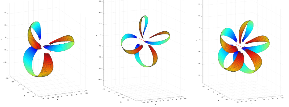
- Parameterization: The code utilizes a base offset table (
getBaseOffsets) representing a reference toroidal propeller design. Users can modify this base design by applying scaling factors to the distributions of pitch, chord, thickness, camber, skew, and rake via the mainParamsstruct ingenerateToroidalProp.m. The hub radius (hubRadius) can also be parametrically adjusted. - Blade Section Definition: A dedicated
BladeSection.mclass handles the generation of the 2D airfoil profiles at each axial station.- It currently implements the NACA 66 (DTRC Modified) thickness distribution and NACA a=0.8 meanline profile using
pchipinterpolation on tabulated data. - The class structure separates meanline and thickness definitions, allowing for easier extension to other airfoil families.
- It currently implements the NACA 66 (DTRC Modified) thickness distribution and NACA a=0.8 meanline profile using
- Cosine Spacing: For improved geometric fidelity, especially near edges and roots, the discretization along both the axial span (
nSpan) and the chordwise direction (nChord) utilizes cosine spacing (getCosineSpacing).
Integration
This codebase is being developed as a modular tool. It is intended to integrate with the established open-source propeller design framework OpenProp, providing capabilities for generating toroidal geometries that can then be used within broader design and analysis workflows.
Implementation Note on Chord/Pitch Distribution:
While the eventual goal is full integration with OpenProp for complete design optimization, I currently use an interim method for establishing initial chord and pitch distributions. This approach adapts multi-row blade theory by Kerwin, Coney, and Hsin (1986) by treating the forward and aft portions of the toroidal loop as distinct lifting surfaces with axial separation then adding a tip correction.
- A vortex-lattice lifting-line method analyzes the forward section to determine the downstream swirl velocity distribution.
- The aft section’s circulation is then calculated, accounting for this incoming swirl and the freestream inflow.
- This process is iterated to meet design targets (e.g., target thrust with minimum or balanced torque, cavitation, or strength limits), optimizing the load distribution between the front and rear parts of the loop.
- The resulting chord and pitch parameters are mapped back onto the toroidal geometry defined by the axial span parameterization.
This works okay for iteration. I can then export the geometry to CFD to develop final performance curves. This function is not up on Github yet.
Ref: Kerwin, J. E., Coney, W. B., and Hsin, C. “Optimum Circulation Distributions for Single and Multi-Component Propulsors”. Proc. 21st American Towing Tank Conference, Washington, DC, 1986.
Usage and Output
- Configure the desired propeller parameters within the
Paramsstructure in the main scriptgenerateToroidalProp.m. - Run the
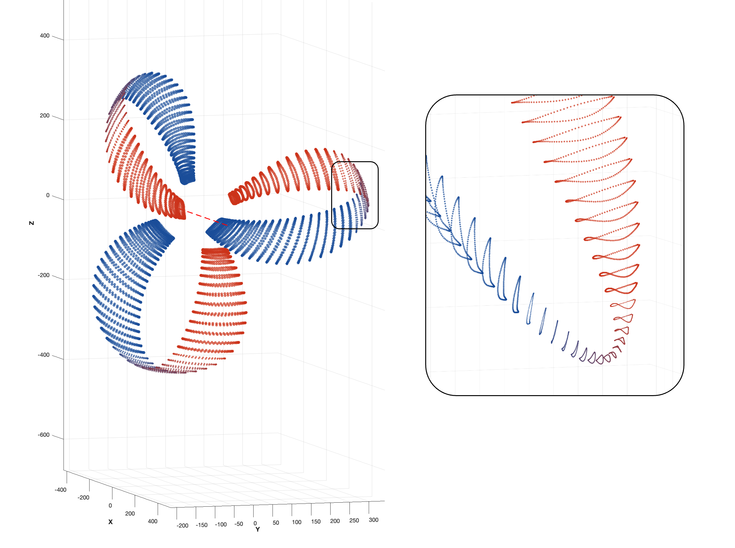
generateToroidalProp.mscript. - The script outputs arrays (
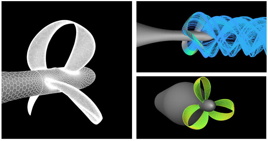
xCoords,yCoords,zCoords) containing the coordinates of points defining the surfaces of a single blade, which are then rotated to generate all blades (allBladesstruct). This point cloud data can be used for meshing, visualization, or further analysis. Plotting and export functions are included. - The exported surface mesh may then be brought in to high-fidelity CFD analysis.
Example CFD Performance Prediction
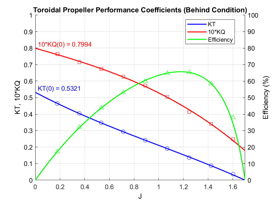
I would recommend finalizing the exported surface mesh in Rhino 3D (e.g., add hub, check for closed surfaces). As an example, I brought a generated geometry into RANS CFD. Using a rotating frame of reference method, I simulated across a range of advance ratios (J = Va / (nd)), varying inlet velocity.
The results are consistent with other published research, where the overall efficiency is generally lower than a standard free-tip propeller. This is not surprising, primarily due to the significantly increased wetted surface area of the continuous loop design compared to traditional open-tipped blades, which results in higher frictional drag. While toroidal designs aim to reduce noise by mitigating tip vortex formation, this often comes with a trade-off in peak hydrodynamic efficiency, particularly in open water conditions. The benefits may become more pronounced in specific applications where noise reduction or cavitation mitigation are paramount.
Repository
The MATLAB source code is available on GitHub, released under the MIT License.